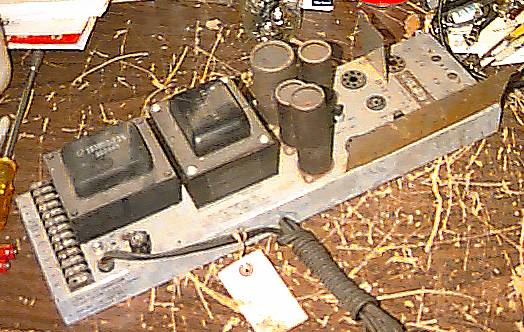
 "As Found"
Often, the tube-audio experimenter finds various tube type "public address" amplifiers available at low cost. While most of these are definitely NOT "Hi-Fi", these same units are rugged, powerful, and can be tamed sufficiently to please all but the most jaded ear. Although a sow's ear cannot be turned into a silk purse, it can be made into a fine wallet! If 40 watts RMS from 20Hz to 30KHz +/-1.5 db sounds good to you, then you might enjoy this experiment.
How to pick a good candidate amplifier:
The most significant problem with public address gear is the use of
audio output transformers which do not have enough iron in them to handle
the lower frequency content at the amplifier's full rated power. Look for
amplifiers in which the output transformer is as large as the power transformer.
The bigger the better! Another problem with the output transformers is
that the laminations are often fairly thick. Many thin laminations are
preferrable to fewer thick ones. The laminations should be much thinner
than those of the power transformer. If the transformer has a 25V balanced
line output winding, then it can then be used to provide power feedback
to the cathodes of the output tubes, which will abate a multitude of evils. Don't
be too picky, remember, these are PA amplifiers! Just try to find a pair
if you want stereo.
The example:
A good example of a suitable amplifier is the Stromberg-Carlson APH-1050.
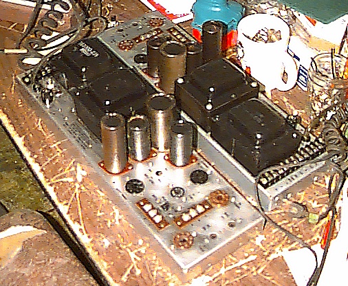
 "AFTER" Note the plate caps on the
6CD6's
"AFTER" Note the plate caps on the
6CD6's
The 'empty' tube
sockets were actally sockets for a remote control and an input transformer,
which were not used. Note the larger transformer to the right is the excellent
large output transformer.
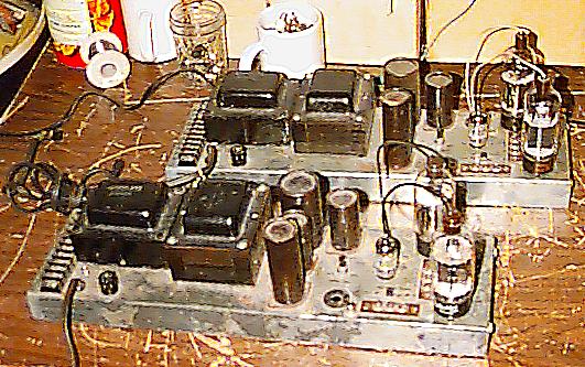
 Results of a cleanup and careful refinishing.
The output transformer is actually larger than the power transformer, and the output transformer also has a 70&25V.C.T. "line" winding as well as the 4/8/16 ohm "speaker" winding. Changes to be made can include different tube types, power supply voltages, and biasing/balancing arrangements. Since the Stromberg-Carlson APH-1050 can use most of these changes, It will be specifically discussed.
In case you may have doubts, see what one very discerning music lover
had to say about the four of these amps I modified specially for him, according
to this exact Article.
"The amps are the best electonics purchase
I've ever made. They are absolutely reliable, do not get too hot, are low
maintenance, have cheap replacement tubes (which I haven't needed yet),
and sound clean and quiet, with good bottom to the sound. They are a very
good match for ar3a speakers, which provide good bass at low cost. The
amps must be high current, as that is what everyone says works best with
ar3a speakers."
-Steve Selby
Please keep in mind that in cases other than the exact model I describe,
slightly different strategies may apply on the road to good sound, but
in any case the principles are identical and "sound".
The original Schematic Diagram:
Choosing different tubes:
The stock APH-1050 uses a 7199 as a preamp/phase inverter, and 7581
outputs. Both of these fine tubes are now expensive. I happened to have
a carton of 100 new 6GH8A tubes, and about 20 new 6CD6G tubes. I decided
to use those, since the amplifier came with no tubes and those new tubes
were on hand.
A check of the tube specifications shows that the 6GH8A, which was
commonly used as a 3.58 MHz amplifier in color TV sets, would be ok for
the driver. A precedent to this use would be that
Sound Valves uses the 6GH8A in their excellent $899
VTA70B/K 35/35W (BLACK) stereo tube amp KIT amplifier
and no one seems to be complaining.
The 6CD6 horizontal-output-type beam power tubes are certainly more
robust than the original 7581's, in fact, they are rated at 200 milliamperes
plate current which is far more than the 7581's 74ma, and even beats the
6550's 175ma.
The 6CD6 uses 2.5 amperes for its 6.3V heater, and this was a concern
since the 7581 uses only 0.9 ampere. This is an important concern, and
must always be investigated when changing tube types. Extended operation
of the transformer with this larger load did not produce any undue heating
of the windings. If in doubt, there is nothing wrong with keeping the original
tubes or installing a separate heater-supply transformer.
The 6CD6 uses relatively low screen voltages, only 180V as compared
to 350V for the 7581, so I took the G2 voltage from the center of the driver's
voltage doubler stack. Ripple and noise from the screen grid current was
checked with a scope and was found to be inconsequential. The Cathodes
were returned to ground through the 25V.C.T. winding on the output transformer
wired in the "bucking" polarity. Each side of the 25V winding is about
1 ohm, so the current in each tube can then be measured by measuring the
voltage between the cathode and ground. The original circuit returned the
cathodes through 10 ohm resistors. I left the resistors in the circuit,
between each of the cathodes and the
25V winding ends, to make bias measurements more easily. Note the original
design applied "shorting bars" across the terminal strips the resistors
were mounted to resistors when the amp was in use, and these were removed
only when bias and balance measurements were being done. The new design
leaves them off. This results in a very slight additional amount of
negative feedback (about 5% effective reduction in grid-cathode drive voltage)
to the output tube. This negative feedback is mostly unimportant in view of the
negative cathode feedback (about 40% effective reduction in grid-cathode drive
voltage), so it was considered simplest to avoid the
need to strap or unstrap such terminals when desiring to make measuments.
The Modified Schematic Diagram
The downside to this cathode feedback arrangement is that almost twice
the voltage drive is required at the grids of the outputs to achieve full
output power. When the voltage amplifier is required to generate almost
100 volts of peak ouptut from a 1 volt input, the sine waveform can become
asymetrical. To get the highest amount of drive from the voltage amplifier
with minimal distortion of the waveform, nearly the highest voltage allowed
in the tube manual was used, and then the G2 resistor of the preamp section
was manipulated while observing the waveforms at the plate and cathode
of the phase inverter on an oscilloscope. This 'tweek' resulted in a 762K
G2 resistor in this case. It may well be asked why an individual G2 tweek
is necessary, and the reason is that the 6GH8, for all its good qualities,
was produced in enormous quantities and varieties, and the characteristics
vary slightly from one manufacturer to another. The input (volume) potentiometer
was bypassed, and then used in series with a 680K resistor to come up with
the 762K that this case required. Alternately the 1M resistor could be
replaced with a 330K resistor and a 2 meg pot. The correct alignment is
easy to make in any case. To align the amplifier, acquire a scope and a
digital volt meter or a meter which has a resolution of 0.1 millivolt.
When the cathode feedback scheme is used, power output is often less
than before due to less apparent grid-cathode drive voltage to the output tubes.
If the transformers and tubes are up to it, the load can be
"tapped up" to the next higher tap and more output power (via increased tube
current) as described:
After the amplifier was modified and aligned, the output from the 8
ohm tap into an 8 ohm load was measured and found to be about 38 watts,
and about 50 watts when the 8 ohm load was driven by the 16 ohm tap. Likewise,
the maximum power was delivered to a 4 ohm load from the 8 ohm tap. Extended
full power operation in this mode produced no unusual temperature rise
from any component. This extra power is a benefit of using tubes with high
current capability and low screen grid voltage requirements.
It may be
noted that with the 6CD6's the limit to 38 watts was caused by insufficient
drive to the grids. Nearly full output (49 watts) was available with an
8 ohm load connected to the 8 ohm tap *after* the driver and voltage amp
supply voltages were raised further from 336V to 380V by changing the 13K
driver decoupling resistor to 1K @1 watt.
Another note on
this amp is that it is convenient to use a 47K to 100K resistor in place
of the volume control, from the 6GH8's pentode section grid to ground.
Tweeking the 18K resistor in the overall feedback path is a convenient
way to adjust the gain of several amps so that they are alike.
Alignment procedure:
Saftey Warning: Electronic equipment contains
high AC and DC voltages, which can be deadly. The described amplifier produces
up to 500 volts DC and 1000 volts AC internally. These voltages are present
on any external plate connections of the output tubes as well. If you are
not qualified to work with such equipment, enlist the aid of someone who
is. Never work alone on high voltage equipment.
This procedure assumes that the circuit is as shown in the 'after' schematic, and applies strictly to that design.
Connect a load resistor to the amplifier's output. Failure to load the amplifier with a speaker or load resistor can destroy the output transformer.
Connect the negative lead of the voltmeter to the center tap of the 25V winding (ground).
Turn on the amplifier. Beware of excessive cathode current as will be indicated on the meter: perform the next step immediately!
Measure the voltage from either cathode to ground.
Adjust the bias control at each tube for 200-220 millivolts DC. This corresponds to 20-22 Milliamperes per tube, flowing from ground through half the 25VCT winding and through the 10 ohm resistor to each of the cathodes. The currents (voltages) should theoreticaly be equal but a difference of up to 10% is OK.
Allow the amplifier to warm up for 10 more minutes with no signal.
check the voltage again. readjust if necessary.
Connect an oscilloscope across the load resistor.
Drive the amplifier with a triangle wave to the verge of clipping at a frequency of 300 to 2000 Hz.
Adjust the voltage amplifier G2 value to obtain as symmetrical and linear a triangle wave as possible. The slopes of the triangle will be very straight when this is done correctly.
Run the amp at 40 watts RMS Sinewave output at 1 KHz for 30 minutes.
Idle the amp with no input and re-check and re-set the bias
Let the amp idle and cool for 20 more minutes.
re-check and re-set the bias
Alignment completed. Enjoy the amplifier.
copyright 1994-Y2K and Beyond Patrick Jankowiak
Visitors since 05/02/99
FastCounter by LinkExchange