A Tube-type Class-A DC-Coupled Plate Modulator for Low Power AM Transmitters
Home
This page is primarily concerned with a method of plate-modulating a class-C RF stage without the usual modulation transformer. The design is no more complex than a traditional high fidelity tube type modulator using a modulation transformer.
Advantages are increased fidelity and stabilized, adjustable carrier level, as well as dispensing with the cost of an oversized modulation transfomer, which may or may not have the 'perfect' ratio desired.
The main disadvantage is low efficiency in the modulator. This is acceptable because the design goal is a modulator to power a SMALL transmitter, for use around the house.
The reason this project was undertaken is simple: I have, for years, reworked old plate-modulated ham radio transmitters for high fidelity operation, and found that by the time everything is done, including operating the transmitter and modulator at much reduced output, the operating conditions are often unsatisfactory due to the impedance ratio of the transformer, and my unwillingness to 'bugger up' collectible equipment.
The target audience is collectors of old tube radios who would like a small but high fidelity tube transmitter through which to feed their CD collection, etc.
The modulator described has been built and tested and is capable of providing a 0-300V voltage swing at a current of 0-80mA. This is enough to power an AM transmitter with a 5 watt carrier and a 20 watt output at the crest of the modulation waveform. More than enough to get one into trouble with the FCC, I'm sure.
The design allows you to set the carrier level and the modulation level independently from almost zero, to the stated specification, with no change in fidelity or circuit components. Yes, you can run 0.5 watt carrier, and modulate it to a 2 watt peak if you like. Cool, eh? The modulator has an adjustment for DC output voltage which is used to set the carrier, and the input amplitude of the audio driving signal is externally set by the user for 100% modulation. More comments, some repetitious, are at the end of the page.
DANGER: The circuitry described herein uses deadly voltages and dangerous power levels. Tubes can become very hot and cause serious burns if touched. Always use caution when building or working on high voltage equipment. God is only a prayer away, and a couple hundred volts is all it takes to meet Him.
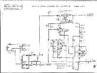
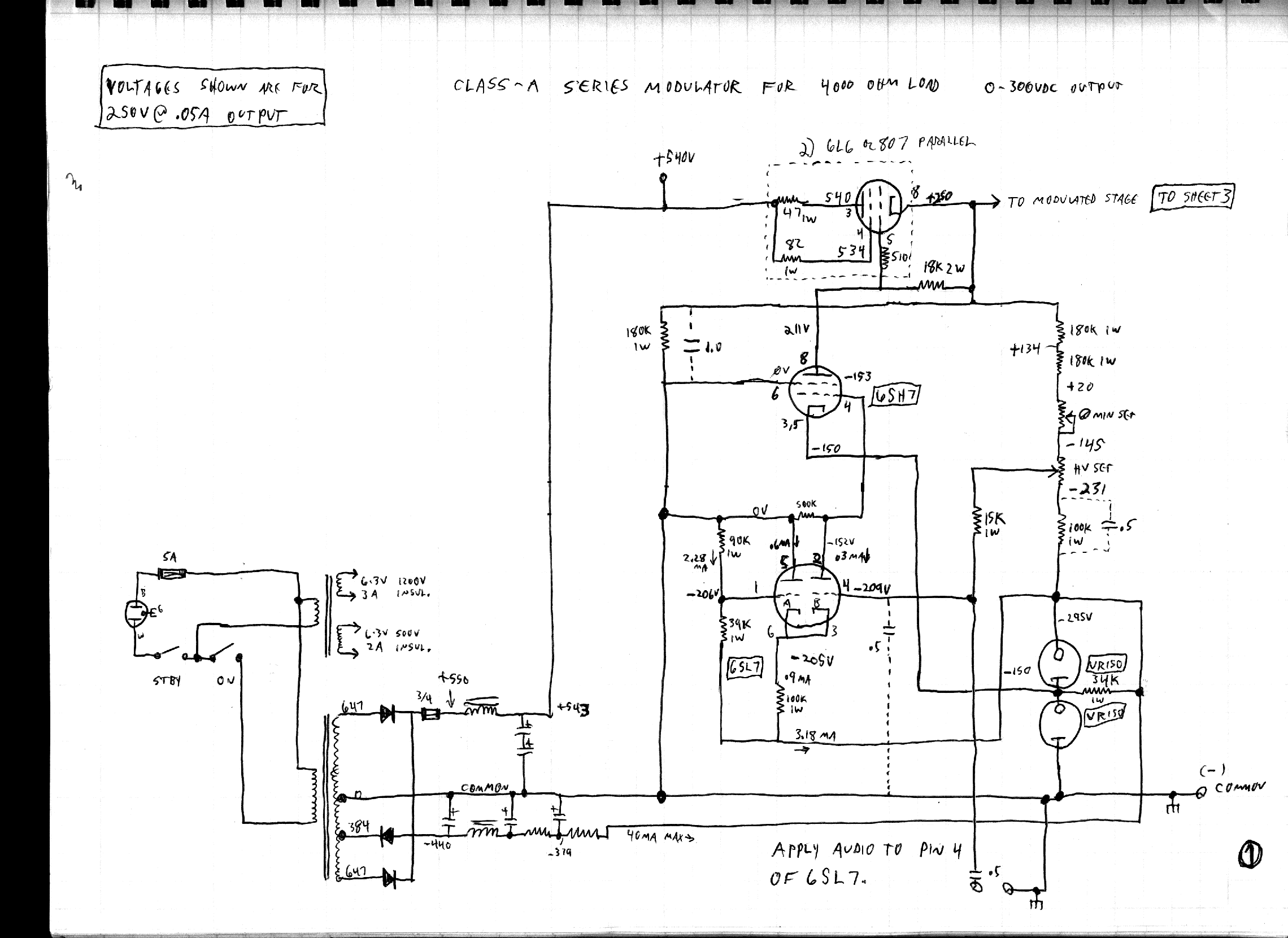
Modulator Schematic. This design is proven by experiment. The modulator avoids the use of a modulation transformer and employs pass-tube technique to regulate its output. Audio voltages applied to the modulator's input are amplified along with any error voltages and supplied to the modulator's output. Avoid excessive audio-frequency reactance in the plate RFC(s) and bypass capacitor(s) of the modulated stage, just as you would in a notmal transformer-coupled modulator.
182.59 Kb
2280 x 1661
|
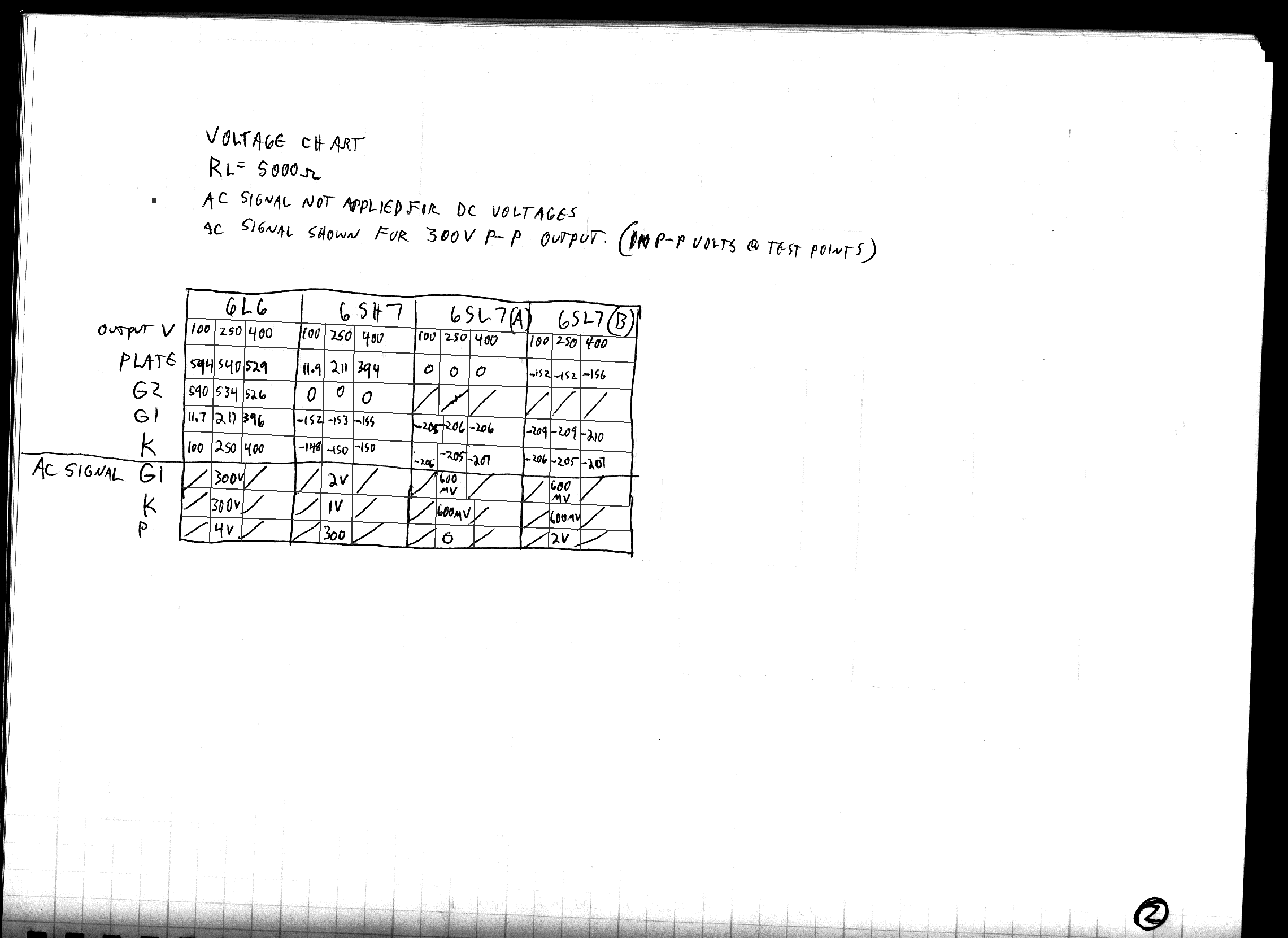
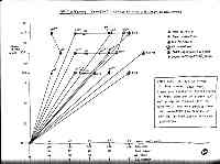
This chart shows the voltages at the critical points of the modulator at output voltages of 100, 250, and 400VDC The output swing of the modulator is from 100 to 400 VDC. For complete modulation, the Final RF stage needs to swing to zero volts. The simple mechanism for this is given in 'sheet3-finalpa.gif' below.
135.06 Kb
2280 x 1661
|
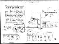
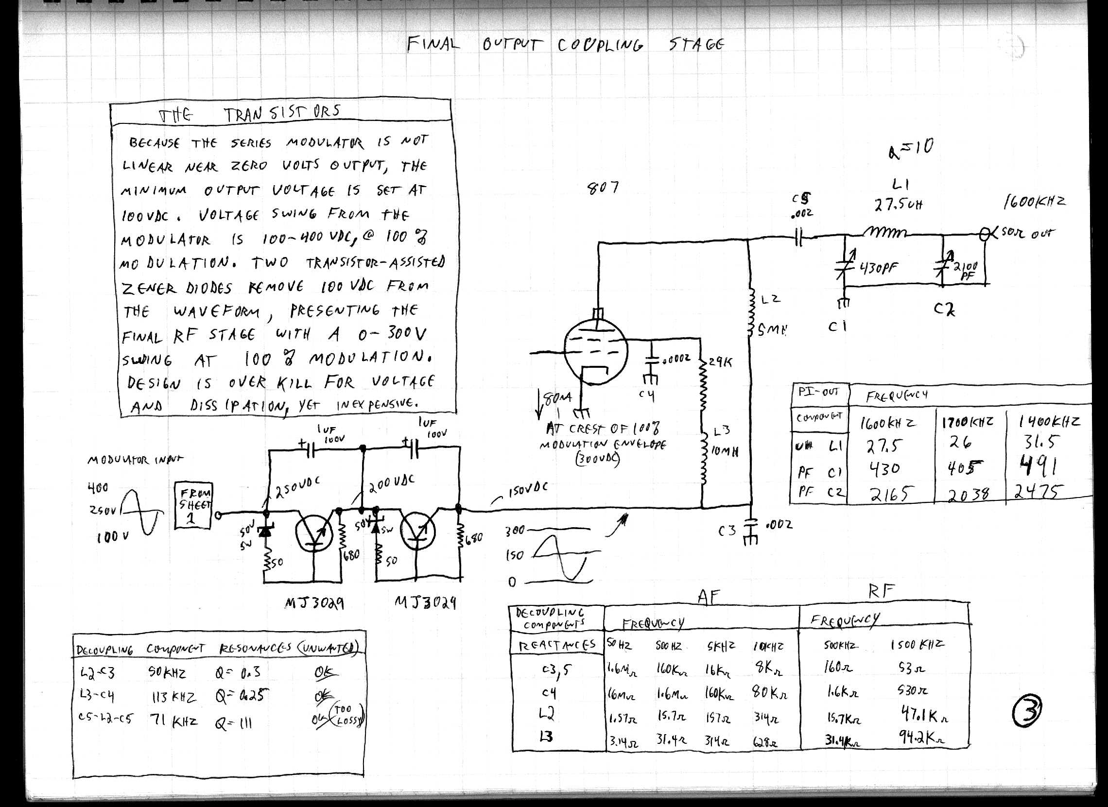
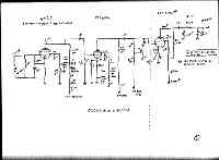
The final stage is shown. This stage is designed to operate at 5-7 watts output with 150VDC applied, which is way more than enough for a simple transmitter for use around the house. This is the carrier condition with no modulation. As can be seen, the modulator's output voltage is reduced in a linear fashion by a simple voltage-eating circuit. This is done because the modulator is not linear all the way down to zero volts, but it is very good down to 100V. Thus, for the modulator's swing of 100-400V, the RF stage is supplied with 0 to 300V. The idea is not to achieve efficiency in the modulator, but to acheive good modulation without an expensive and restrictive modulation transformer. A chart of reactances which should be watched out for is shown as well. Too much reactance can affect frequency response. Frequency response should not be limited in a properly designed modulator and coupling system, but before it.
279.09 Kb
2280 x 1661
|
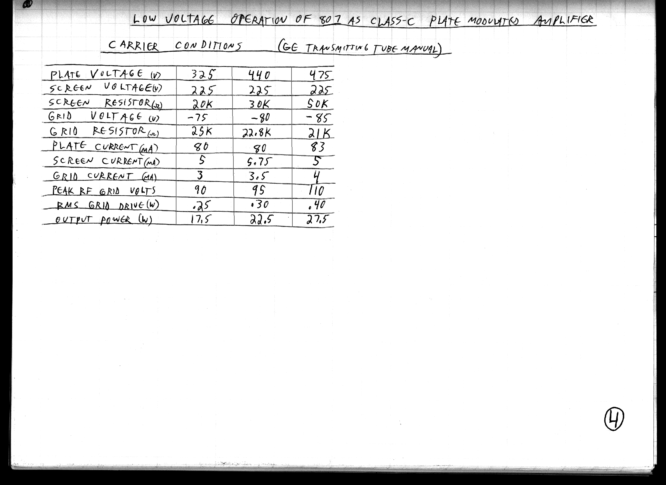
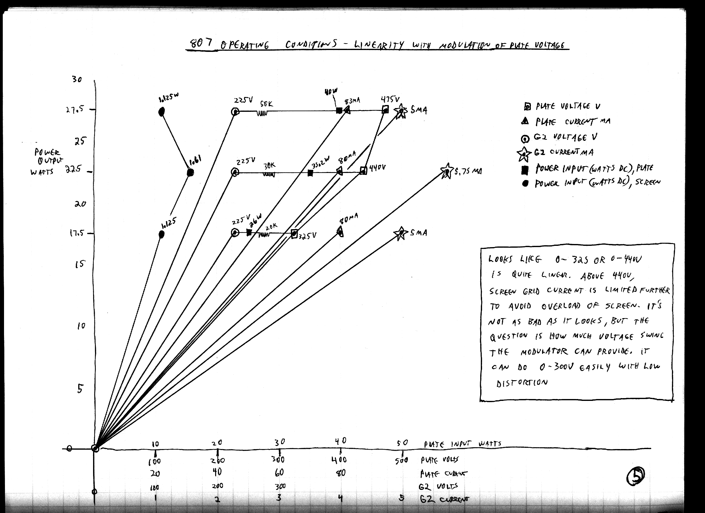
published conditions for the 807 in this service, extrapolated from the 1956 GE five-star and special purpose tube types manual, which lists the 807 operating at low voltages of 325-400 and gives values for screen dropping ressitor as well.
181.77 Kb
2280 x 1661
|
somewhat theoretical conditions postulated for the 807 in this service. The chart assumes the tube as a constant impedance load. In actual practice, it is not so perfect, but the modulator has a low impedance and will regulate the voltage correctly over the excursions of the audio waveform.
178.04 Kb
2280 x 1661
|
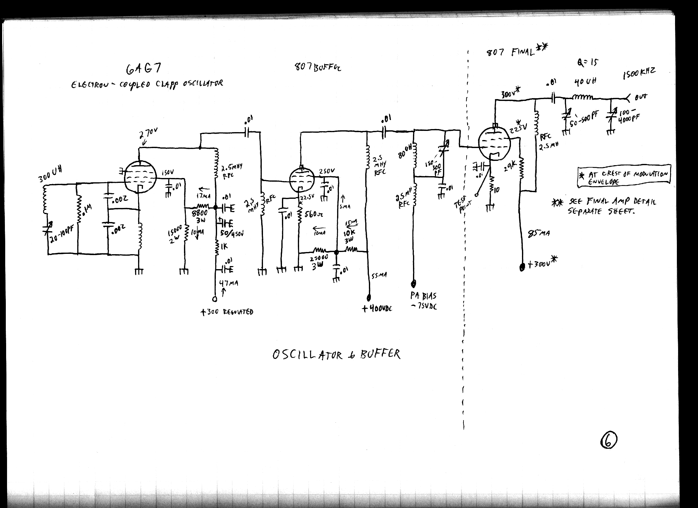
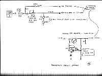
electron Coupled Clapp oscillator (VFO) and class A buffer to drive the final tube.
142.80 Kb
2280 x 1661
|
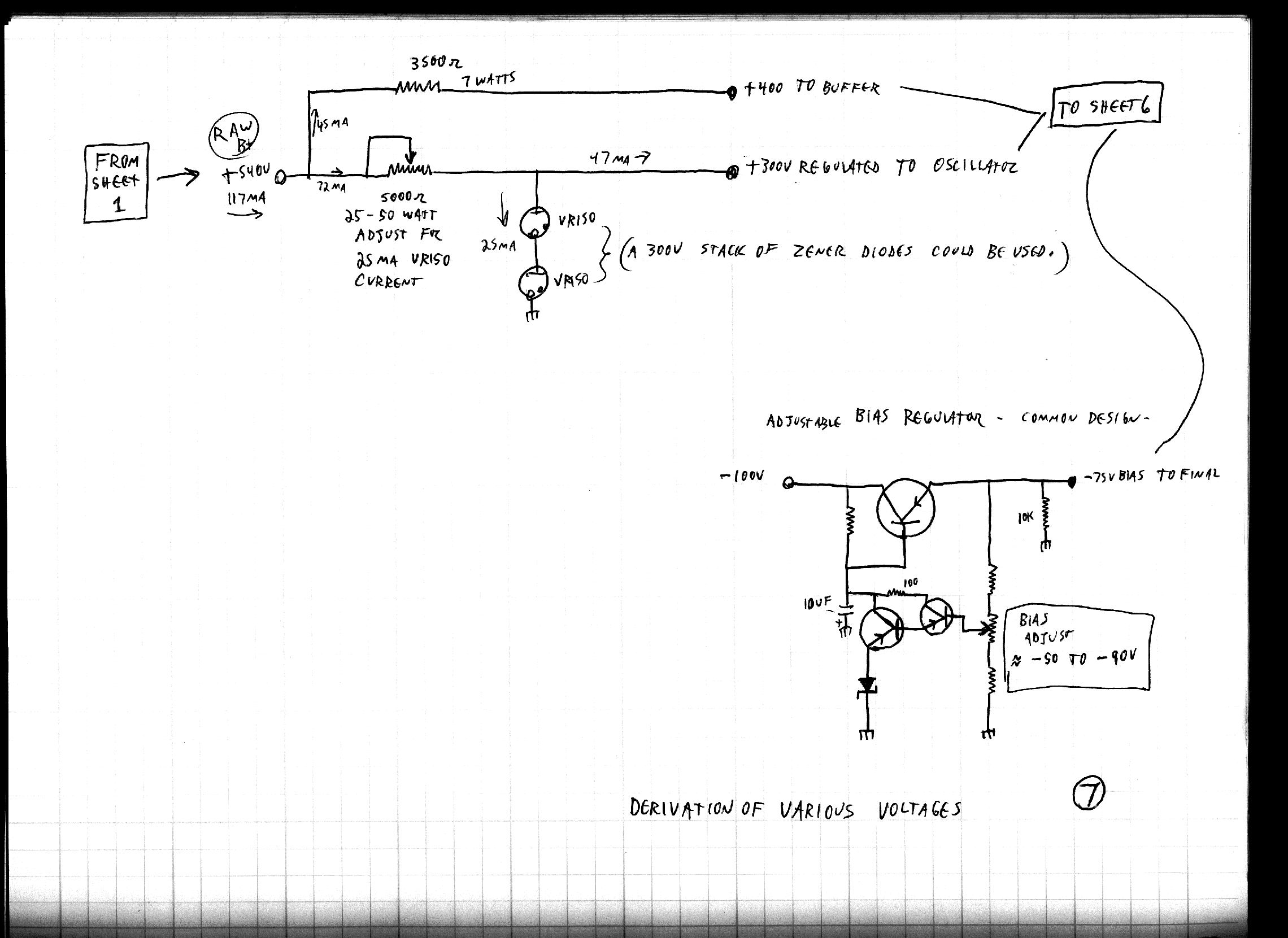
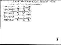
alternate methods of obtaining various votages for the buffer and oscillator.
160.92 Kb
2280 x 1661
|
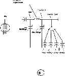
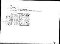
sample pi-network values. You can calculate your own with the PIOUT.EXE program contained in this zipfile(intel only), or any one of a number of others, or just do it the old fashined way, with the books of Terman and Orr. You'll have to experiment a bit with this anyway, unless you do it all the time, but these should get you into the ballpark. Get your grid dip meter warmed up!
5.47 Kb
580 x 864
|
Comment 1.
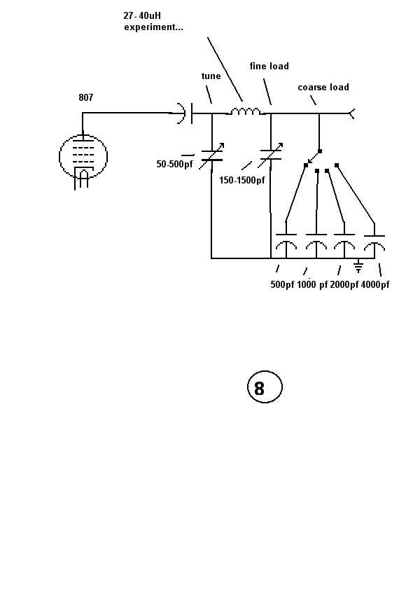
Sheet 3 and 6 show different values for the pi-network for the final stage. Sheet 3's values were calculated by the PIOUT.EXE program. Sheet 6's pi-network values were copied from a book showing a 160 meter rig. This sort of thing is where experimentation is always required. 400pf for the input capacitance and 2000 for the output capacitance are fairly close, but in the experimental model, you may wish to use a ceramic rotary switch to switch in a progressively larger amount of capacitance in parallel with the otherwise impracticably large output capacitor. This suggestion is shown in sheet 8.
Comment 2.
The modulator is actually almost a copy of a classic tube-type variable-voltage regulated power supply. The design has been modified to enable fairly linear modulation of the output voltage. The fidelity is as good as any class-A amplifier. This part of the circuit has been tested and proven, but I left lots of room for tweeking. The power transformer shown in Sheet 1 has a tap for 384 volts. This is not easy to come by, and it is easy enough to use two transformers. The 380V transformer, can be used to power the +300V and +400V for the oscillator and buffer. This will improve regulation for those stages. You can of course use any kind of rectifier and filter arrangement you wish, based on what transformers are at hand. This gives lots of leeway in picking transformers. Although gas regulator tubes are shown, you can of course use zener diodes or transistor-assisted zeners. You can put a large capacitance across a zener, but never across a gas regulator, or it will oscillate because of its negative resistance characteristic. The best power supply design freeware I have found is that by Duncan. It is much better than mine (which is old but included anyway in the zipfile above), and I reccommend it highly.
Comment 3.
Sheet 1 also shows the modulator delivering 50ma. It will do 80ma ok on modulation peaks. The final amp will use about 40ma at carrier conditions (250V output from the modulator). This gives 300V across the modulator tubes. Since the screen grid is effectively tied to the plate voltage, and the maximum screen grid voltage rating for the 807 is about 300V, this might cause a problem when the modulator swings down to 100V at the negative modulation peak and the tubes have 440V across them. That is why I recommend the 6L6GC type. The 807 will probably work ok in this service, and you'll just have to try it. If you blow one up, that answers that question. Note that the resistors in series with the grids and plate of the modulator tubes are 'per tube' to avoid / prevent parasitic oscillation.
Comment 4.
For the modulator's power supply, the cleaner the voltage going to the circuitry, the better. Any ripple will be amplified and show up in the output. The 6SH7 tube stage has a voltage gain of about 150, so the more silent the power supply, the better. You can see some dashed lines where capacitors are ghosted in. These would be used, IF the circuit were to be used as a variable voltage regulated power supply. They are not used when the circuit must handle audio frequencies. The stack of capacitors across the 540V rail should be at least 200 uF (400uF each). To avoid excessive peak currents through the diodes, a choke input filter with about 10H is recommended. Again, the Duncan program..
Comment 5.
In sheet 1, the heaters of the modulator tubes (6L6) are at a high voltage (100-400VDC). Use a separate filament transformer rated for at least 1000 volts hi-pot test on the 6.3V winding to ground and the primary. Check the heater-to-cathode ratings of the tubes in the manuals and you'll see what I mean.
Comment 6.
Do you have a grid-dip meter? It will be very valuable when checking for what resonant frequencies your tuned circuits are actually tuning to.
Comment 7.
All is subject to change. Have fun!

FastCounter by bCentral