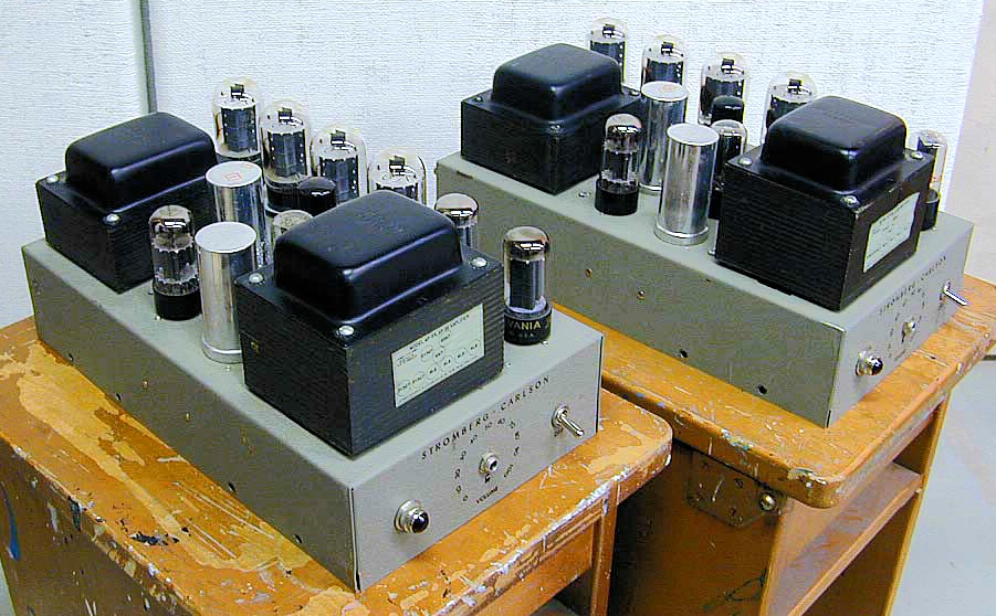


Here we have a very cool amplifier, the stromberg-carlson AP-55 / AP-56. They are electronically alike except for the input transformer which the '56 does not include. The same schematic was provided by Stromberg-Carlson for both amps. The original schematic included notes regarding the 55/56 model differences as well as the optional standby relay which cuts off B+ and an adjustment of gain involving the input circuit. Those notes are reproduced in the "original" schematic. The complement of four 6L6G output tubes operating close to class A with a common cathode bias resistor is typical of period power amp circuits. In its native state, the amp performs listenably, but is subject to minor sonic problems caused by unequal output tube current, high idling current, and a few small sins of the output transformer, which, although decently large, really needs to be included in a power feedback loop with the output stage tubes' cathodes.
The amplified signal present at pin 2, the plate of V1A, is passed through a two pole variable frequency filter composed of C3, C4, R8, R9, and R10A/B, to V1B grid pin 4.
The signal is further amplified in V1b and the large signal present at the plate pin 5 enters a three way matching network composed of C12, R13, C5, R31, C13, and R28. The center of this network feeds the signal, now frequency-compensated and mixed with negative feedback from the output of the amplifier, to V2A grid pin 4. The network circuit is responsible for most of the the overall small-signal (linear operation) gain control and frequency response of the amplifier
V2A amplifies the signal and drives the 'top' pair of 6L6 output tubes from its plate at pin 3, and also provides a small signal to V2B grid pin 5 through voltage divider R15 and R16.
V2 has both cathodes tied together internally and they exit pin 8. A 2200 ohm resistor R22 provides bias to V2, and since no bypass capacitor is used, R14 provides a certain amount of common mode noise rejection in this class-A stage.
V2B amplifies the signal from the R15/R16 voltage divider and V2B's plate (pin 6) provides a signal which is 180 degrees out of phase with the signal at V2 pin 3. The out-of-phase signal drives the 'bottom' set of 6L6 tubes. The gain of the stage must be 22.36, to match properly the voltage division ratio provided by R15/R16. Understandably, this could cause problems if the 6N7 should deviate from uniformity or sectional similarity.
The output stage is straightforward, except that screen suppressor resistors were used on only half the output tubes, ostensibly to save money. No plate suppressors were used. Output stage bias is provided by R27. The AC-like components of the cathode current flow through C9 and are well-bypassed for signals above approximately 300 Hz. Below this frequency, gain reduction sets in due to the signal voltage drop across R27 and the lower frequencies are attenuated to some degree.
The original schematic shows the output transformer secondary with taps in what seems to be an incorrectly labeled order. The output connector J1 is a 9-pin keyed socket which is very similar to, but incompatible with, the plug for an octal tube socket. The primary impedance of the transformer is 4500 ohms CT. The secondary provides 4, 8, and 16 ohms, as well as 25VCT and 70VCT line outputs. The feedback winding is 32 ohms nominal impedance, but is not designed to carry power, only to supply feedback voltage.
Assuming that the amplifier is operating at the 50 watt level, which is reasonable for a set of four push-pull parallel 6L6G tubes, these RMS voltages, impedances, and currents would be present:
The reasons for modifying the AP55/56 follow the schematic which embodies the proposed changes.
John Horn asked for some ideas on how to improve the amplifiers, and sent the schematic. After analyzing the circuitry, the following suggestions are made. A goal was and is to keep the basic signal path fairly similar to the original, so that the amplifiers' identity is not lost. Of course the original design clamors loudly for certain improvements. One need not perform every one of the modifications suggested, but a good hack attack is definitely needed!
The input transformer was removed from the circuit, as it will not be needed in a home hi-fi scenario.
The bass cut circuit was removed for the same reason. If the amp were to be used in a biamp or triamp scenario, it could be left in and used, but it causes much phase shift over the frequency range, and it would be much better to employ an active crossover.
The audio coupling capacitors were increased to 0.2 uF, for good low frequency response. 0.22 or 0.33 uF would be fine as well. Much more than 0.33 and the amp could become subject to charge-discharge effects when temprarily overdriven and experience recovery-time issues due to the resultant power supply voltage excursions.
The cathode bias scheme was abandoned. A bias supply was designed to provide individually adjustable 0-40V negative voltage to each 6L6 control grid. The amp will no longer require closely matched tubes, although they are always a plus. The individually adjustable bias allows the listener to set the operating point anywhere along the load line for each tube. The amp will no longer consume tubes at a high rate, running near class A, unless you want it to.
The bias supply operates with a half wave rectifier on the secondary of the power transformer. The design uses a 30K 5w resistor to permit about 10mA of peak current to flow through a 1KV rectifier diode. This current keeps a 100uF 160V capacitor charged, and the voltage across the capacitor is regulated by a 40V 5 watt zener diode. Four 250K pots are placed across the 100uF capacitor. the wipers of the pots are bypassed by 4.7uF capacitors. These four quiet, adjustable voltage sources each provide a voltage with an impedance which is low compared to the resistance of the pots and 100K resistors leading to the output grids. While there may be temptation to increase the size of these 4.7uF capacitors, it should be kept in mind that too large a cap will make for a very slow reaction to an adjustment of the bias control. The control grid circuit resistance presented to each output tube is about 100K. The load resistance presented to the 6N7 driver by these 100K resistors is 50K per plate.
The power supply needs some changes. A 100uF capacitor was placed across each section of C11 and across C1C and C1D. A 40uF cap was placed across each of C1A and C1B. The plate supply 5Y3 tubes can be removed or left in place for appearance, but they are close to being overworked with the peak current required by the larger filter cap, and at full power they allow a large voltage drop. Each one was bypassed with a 1KV/1A diode in series with a 100 ohm 5 watt resistor. Room permitting, they could be replaced with 5V4 types which have the same heater power and base pinout but less voltage drop and higher peak curent ratings. The 5Y3 that powers the screen grids and preamp section may be left alone as it is under a very light load.
Parasitic oscillation suppresion measures were improved. Plate resistors of 50 ohms 1 watt were added to each 6L6 at pin 3. Two additional 220 ohm resistors were added to the screen terminals at V4 and V5. If any parasitics appear, as they often will on the crests of waves at high power levels, a 22-100pF disk ceramic capacitor can be placed between the first (top) 6N7 plate and ground. Other locations may also be tried. Use the smallest possible capacitor.
To improve speed and linearity of the output stage, the cathodes of the output stage are coupled through part of the secondary winding of the output transformer. At the theoretical full output of 50 watts, using the 25VCT winding for cathode feedback, each cathode receives 17.6 peak (12.5 RMS) volts in opposition to the flow of cathode current. This voltage must be made up by the 6N7, but this is not a problem. Optionally, the voltage to the driver stages can be raised to obtain more drive. If this is done, the driver bias resistors may require changes. The correct polarity of cathode connection for negative feedback is that which gives less output voltage for a given small signal input voltage. Alternately, the 0-4-16 ohm taps could be used, providing a little more (14.14 V RMS) of this beneficial negative feedback.
To provide an easy way to measure not only the resting current, but also to measure the relative performance of each output tube, a 10 ohm resistor was placed in series with each cathode. Each cathode now becomes a 'bias test point'. When the amplifier is idle, the current through an output tube in milliamperes is equal to 1/10 of the voltage present at the cathode in volts. When the amplifier is driven to near maximum output, a prefectly matched set of tubes would show identical voltages at the cathodes (The voltmeter is set to DC for this because even though the voltage present has a very large AC comopnent of 12VAC or so, the DC component of 1.5-2VDC is what is used to compare the relative current through each tube.)
The 6N7 is used as a high gain phase inverter. Not all 6N7 sections are created equal, although most are very close. Additionally, the 'top' 6L6 pair may have a higher or lower cumulative gain than the 'bottom' pair of 6L6's. Power supply voltages cause differences in gain. To improve the symmetry of the stage and the amplifier overall, the voltage divider was made variable. The stage is most easily aligned with a triangular wave.
6L6G types were retained. One can also easily use the 6L6, 6L6GA, 6L6GB, 7027, or 5881. Use of the larger 6L6GC is not necessary, and little additional benefit will be realized by its use, other than extended tube life. This is because the plate voltage is only 390V (no signal) which is ok for the 6L6/G/GA/GB, but it's kind of low for making maximum use of the 6L6GC which likes 450V. The current ratings are about the same, so no power benefit is to be obtained by heavier loading (i.e. putting a 4 ohm load on the 8 ohm tap). Other tubes can be used as well, just be sure to check the pinouts on the tubes against tube socket pins used as tie points!
Necessary Alignments BEFORE Operation:
To align the amp, obtain an oscilloscope, a function generator covering 400-2000 Hz with triangle and sine wave, and a digital voltmeter with a 200mV scale. Always connect a load to a tube amp when it is turned on, regardless of signal input! Failure to do so can destroy the output transformer! Load the amp with an 8 ohm load connected across the 0-8 ohm terminals.
Bias alignment: Turn all bias controls to Maximum Bias. Short the input terminals. Set the DC Volt scale on the DVM to 200mV. Put the negative lead into the ground test point jack. Put the positive probe into the first bias test point jack. Observe the reading. For each 10mV displayed, the tube you are measuring is drawing 1 mA of current. set the first bias pot to give a reading of 300mV (corresponding to 30mA). Go on to set all 4 tubes to 300mV reading on each of their jacks. note that you will have to go through this about three times, setting tube 1, then 2, 3, and 4. This is because the settings affect each other slightly due to small plate supply regulation imperfections. Finally, all 4 jacks read in the range of 290-310 mV, an acceptable deviation being a range of 20mV.
The current can be set higher, but beware not to exceed the plate ratings of the tubes. The 6L6G is rated for 19 watts continuous dissipation, corresponding to 487mV (48.7mA) reading on the DVM at a plate voltage of 390. Note that operation at this level will severely shorten the life of the tubes to perhaps a few months, and invite catastrophic failure. Operation at 300mV (30mA) will allow the tubes to last for many years and help the amplifier run much cooler. Very slightly more power was obtained at 350mV (35mA), but is it worth the stress on the transformers in your classic 50 year old amp?
Symmetry alignment: Drive the amp with a 1 KHz triangular waveform until an output of 20 volts peak to peak is seen on the scope. Adjust the drive to the amp so it is at the verge of clipping, and adjust the symmetry control for the best triangle wave, with nice, straight ramps all the way to and from the peaks. go back and forth with the symmetry control and the drive until the largest undistorted triangle is seen on the scope. Lock the symmetry pot in that position.
Burn-In: Run the amp at 30 watts sinewave output at 500Hz for an hour. remove the input signal and wait 15 minutes. recheck the bias currents and readjust if necessary. Perform all alignments once a year, or when you replace a tube.
SAFTEY WARNINGS:
Danger:
Under certain conditions, such as when it has been turned on, this amplifier can produce deadly DC voltages in excess of 400 volts and deadly AC voltages in excess of 800 volts. Tubes and other components can reach temperatures of several hundred degrees. Never touch the chassis or a ground with a part of your body when probing for voltages. Always use a grounded power cord. Keep one hand in your pocket when probing or measuring. Never use a larger fuse than specified in the instructions or on the equipment. Never work alone on high voltage equipment. If you do not understand the hazards of this kind of work, enlist the aid of someone who does, such as a professional technician or possibly a hardware hacker or an amateur radio enthusiast. Old guys who repaired RADAR gear or transmitters in the military are highly recommended as mentors! Respect them and listen carefully to their valuable wisdom concerning such matters! Don't fry yourself. God is only a prayer away, and a couple hundred volts is all it takes to meet Him.
Are you now or have you ever been an AP-55 or AP-56 owner? Invitation:
If you have this kind of amplifier and have improved it or are considering improving it, please do not hesitate to exchange or request information. I would like to hear about your Stromberg Carlson AP-5x, and add a link from the Official Stromberg carlson AP-56/56 Shrine to your own excellent Stromberg carlson AP-56/56 page.
Contact: [email protected]
Pages copyright Pat Jankowiak 1997-Y2K