The original circuit
 Top View.
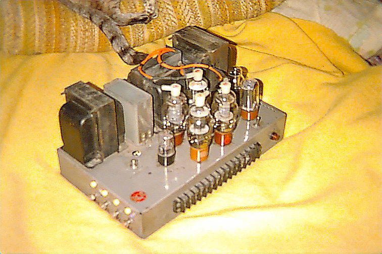
 Side View -added bias pots and test points.
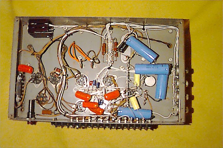 Bottom View after rebuild and mods.
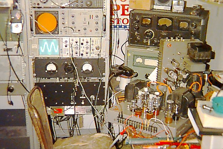 Thorough Testing.
Introduction to the wonderful and beautiful RCA MI-12188A Amplifier
As-Is, These amps are adequate public address voice-range drivers, capable of about 65 watts at clipping from 200 to 15,000 Hz. They also run near class-A, and consume the 807 output tubes quickly. They are definitely not designed as "Hi-Fi" amps, but can be tamed and reworked into a fast, transparent 45 watt amp, and trained to be conservative with those costly NOS WWII JAN-807's.
The original circuit
The original design, born of the post-WWII glut of 5U4's, 0D3's, 6SL7's, and of course RCA JAN-807's, is fairly tough, except that the output tubes dissipate 20-30 watts at idle depending on the individual tube. In those days, however, 807's were American-Made, more uniform, robust, and quite available, and RCA made both the amplifier and the tubes to populate it, just as they had previously done with military electronics equipment during the second world war.
As can be seen, a 120 ohm cathode bias resistor is used, and not bypassed. The tubes run very hot, some even showing a little color in case of a mismatched set.
The filter choke is about 15 henries, and the 14uF B+ filter is barely adequate, but performs well enough in a PA application.
A 6500 ohm 40 watt resistor drops the 680VDC plate supply down to 315 volts, shunt regulated by a series string of 0D3's with a 0.05uF capacitor connected in parallel with the string, to discourage 0D3 RF noise. The +315VDC supplies each of the screen grids through 100 ohm parasitic suppresser resistors, and passes through a 2700 ohm 2 watt resistor to a 30uF/400VDC electrolytic capacitor for final filtering of the driver stage plate supply of 300 volts.
Because of the thrifty design of the power supply, a special "hum cancel" control couples a small adjustable amount of AC ripple from the plate B+ line to the phase inverter's cathode. DC is blocked by the 0.5uF capacitor. The circuit is designed to cancel the 120Hz (2 x AC line frequency) ripple.
The input circuit surrounding pins 4,5,and 6 of the 6SL7 is, to say the least, bizarre, imparting small amount of instantaneous DC plate voltage from the "top" 807's to the (pin 6) cathode of the voltage amplifier. The grid (pin 4) is returned through 470K to a DC value of half this cathode bias voltage. This circuit is rumored to have been designed to provide an equalization curve complimentary to the audio tracks of period motion picture media. The plate (Pin 5) of the 6SL7 voltage amp drives the grids of the "top" pair of 807's through a 0.1uF capacitor. About 7% of this grid drive voltage is picked off and fed to the grid (pin 1) of the second section of the 6SL7, which inverts and amplifies the signal to drive the "bottom" pair of 807's. All of the 807 grids are fed through 6800 ohm parasitic supressor resistors.
The output winding of the transformer is straightforward, providing for 4, 8, 16, 72, and 143 ohm loads. The amplifier performs well loaded either in the manner of 1:1, i.e., 8 ohm load to the 8 ohm tap, or 2:1, i.e., more lightly, with the 8 ohm load connected to the 4 ohm tap.
The power input is worthy of note: that is, there is a tap for 105 volts as well as 125 volts. Always use the 125 volt tap, unless you are POSITIVE that the voltage never rises above 105 volts! In Japan, where 100 volt 50Hz power is present, please try the 105 volt tap, but beware to check for excessive transformer heating due to the 50Hz power.
Fixed Bias:
Increased Grid Drive and Grid Impedance:
Phase Inverter Adjustment:
Overall voltage feedback and Cathode Feedback for the Output Stage [ALA McIntosh or Quad]:
Provisions for measurements:
300V Regulator Circuit and Filters:
The PCB-Filled Oil Capacitor:
Results:
Necessary Alignments BEFORE Operation:
Bias alignment:
Turn all bias controls to Maximum Bias. Short the input terminals. Set the DC Volt scale on the DVM to 200mV. Put the negative lead into the ground test point jack. Put the positive probe into the first bias test point jack. Observe the reading. For each 10mV displayed, the tube you are measuring is drawing 1 mA of current. set the first bias pot to give a reading of 200mV (corresponding to 20mA). Go on to set all 4 tubes to 200mV reading on each of their jacks. note that you will have to go through this about three times, setting tube 1, then 2, 3, and 4. This is because the settings affect each other slightly due to small plate supply regulation imperfections. Finally, all 4 jacks read in the range of 190-210 mV, an acceptable deviation being a range of 20mV.
The current can be set higher, but beware not to exceed the plate ratings of the tubes. the 807 is rated for 25 watts continuous dissipation, corresponding to 417mV (41.7mA) reading on the DVM. Note that operation at this level will severely shorten the life of the tubes to perhaps a few months, and invite catastrophic failure. Operation at 200mV (20mA) will allow the tubes to last for many years and help the amplifier run much cooler. Very slightly more power was obtained at 250mV (25mA), but is it worth the stress on your classic 50 year old amp?
Symmetry alignment: Drive the amp with a 1 KHz triangular waveform until an output of 30 volts peak to peak is seen on the scope. Adjust the drive to the amp so it is at the verge of clipping, and adjust the symmetry control for the best triangle wave, with nice, straight ramps all the way to and from the peaks. go back and forth with the symmetry control and the drive until the largest undistorted triangle is seen on the scope. Lock the symmetry pot in that position.
Burn-In:
Run the amp at 40 watts sinewave output at 500Hz for an hour. remove the input signal and wait 15 minutes. recheck the bias currents and readjust if necessary. Perform all alignments once a year, or when you replace a tube.
SAFTEY WARNINGS:
Simpler mods - Fixed Bias Only
Of course, one can use any or all of the mods shown in the SUGGESTED FULL MODIFICATIONS, in combination, whatever one prefers. Hey, they're your amps, far be it from me to suggest you go drilling holes in them!
Peter's beautiful condition MI-12188A's:
Are you now or have you ever been a MI-12188A owner? Invitation:
Suggested Full Modifications
In the modified version, the cathode bias was replaced by a fixed bias arrangement. The fixed bias power supply is actually a transistor-assisted Zener diode, placed in the center tap of the power transformer HV secondary. This produces a stable -59V source, across which four 200K pots are placed, one for each output tube. This avoids having to match the tubes so closely. The wiper of each pot is coupled to ground through a 4.7uF 160V electrolytic capacitor, and the bias voltage at these points fed to the grids of the output tubes through 250K resistors. It was considered that adding solid state components to a real tube amp like this one might be viewed as a bit pagan by the church of the evacuated, but it is maintained by the engineering staff of DEFBOO.CMD that power supplies are excellent places for the use of solid state devices.
The four 250K grid return resistors at the 807 grids provide a lighter load for the output of the 6SL7 driver stage than the two original 100K resistors. The concern is that the driver not be excessively loaded. the modified output stage will require a little more drive to overcome the negative cathode feedback. The amplifier should be fully driven by a 2 volt p-p signal.
The voltage-divider style of phase inverter is basically OK, but needs to have an adjustment, so that the drive to the inverted gain stage can be made correct, to compensate for the fact that not all sections of dual triodes are exactly alike. A 1.5 uF capacitor and a 1.7Meg adjustable resistor chain (1.5M + 200K pot) provide drive to pin 1 of the inverting stage. The phase inverter and driver circuit could have been completely redesigned, but this mod works well and is more like the original "holy" RCA design. The coupling capacitors to the 807 grids were increased to 0.2uF. 0.2 may seem small, but it's just fine considering the 250K grid resistance.
Disadvantages of this particular implementation are that when the first triode clips on its positive swing due to output tube grid voltage crossing zero in a positive direction, the second (inverting) stage will faithfully reproduce the clip on its negative swing at this same time. There is also no reciprocal clipping of the negative swing of the first stage's plate waveform due to any positive clipping of the second stage's plate waveform. Alone, the overall result adds a few minor imbalance artifacts at clipping, but the negative feedback used elsewhere minimizes this. Anyway, one should not be clipping the fine old amp.
Note that the chassis ground/B- connection of the output transformer secondary is now moved to the 4 ohm tap. This is expedient because any negative feedback voltage which is to include the entire amplifier in the loop (and it should, as the output transformer is not so perfect) must be returned to the first stage, rather than to the inverting amplifier alone. Were the "0" terminal of the output transformer used as common, the phase for this negative feedback (which would then be taken from the 4 [or other] ohm tap) would be reversed. The overall voltage feedback made for a net -6db gain change. The cathodes, now freed from the (removed) 120 ohm bias resistor, are connected in the negative feedback mode to the 0-4-16 Ohm taps on the secondary of the output transformer. The cathode feedback arrangement results in a signal voltage at the cathode which is in phase with the voltage at the grid, and about half the amplitude of the grid drive voltage. This cathode feedback increases the peak grid drive requirements to nearly double, as the cathode and grid waveforms have many in-phase components, and this tends to cancel a portion of the grid drive, since the drive is referenced to ground. The effect of the negative cathode feedback at the output tubes is to help abate the several sins of the output transformer. The cathode feedback provides about -2db gain in any case. The driving circuits must therefore be capable of supplying a peak to peak voltage equal to the bias voltage of about 30 volts, plus the peak voltage across the part of the output winding connected between the cathode and ground, which is about 30 volts. This 60 p-p volts must be supplied without distortion, and the new parameters for the voltage amplifier and inverting stage accomplish this without a problem.
DC Bias/Balance: Each 807 cathode has a 10 ohm resistor between it and the appropriate transformer connection, which makes measuring the quiescent current very easy. There is a test jack conneced to each cathode. A meter measures the DC millivolts between the test jack and ground (this voltage drop includes not only the 10 ohm resistor but also includes a part of the output transformer secondary, but it is less than 1 DC ohm, so we can safely ignore it). The amp idles at 20ma per tube, which is 12 watts dissipation at 600V, and shows up as 200 millivolts DC at the test jack. the CCS rating of the 807 is 25 watts. With individual bias adjustments for each tube, the current is easy to set.
Tube Merit: An additional advantage is the ability to check the relative contribution of each tube to the overall output. When the amp is driven to near-clipping, the DC voltmeter can be placed at the cathode (test jack) of a tube, reference to ground. The voltage is compared to the voltages present at the other cathodes. If one of the tubes reads 0.430VDC, and another reads 0.240VDC, you can be sure that the one reading 0.430VDC is working much harder. In this way, the design has a built-in means for checking the amplification match amongst quads of tubes.
Opinion: I did not make the AC grid drive adjustable for each tube because for a certain individual tube, only a certain amount of peak plate current will be drawn when the grid reaches its positive peak of zero volts. The result of making the drive adjustable and then balancing it for equal signal current amongst the four tubes would be to limit the performance of the better tubes in the quad to that of the worse. It is preferable to simply select four tubes which are fairly close as found after burn-in in an operational test. In cases where there is considerable variation (for instance- you get readings of .430, .500, .250, and .320 under the Tube Merit measurement above), the advantage of a quad of tubes is that you can place the individuals on same or different sides of the push-pull circuit to add their currents together in the output transformer. (for instance you might put the tubes reading .430 and the .320 on the "top" side and the ones reading .500 and the .250 on the "bottom" side, so that the "push" and the "pull" have both a value of .750) Some audiophiles and people who want to sell you things would say that this is blasphemy, but it is the opinion of the engineering staff of DEFBOO.CMD that this is clean and acceptable practice. Your ears are the judge.
The 6500 ohm 40 watt resistor was replaced with a 10K 30 watt resistor, allowing the 0D3's to run cooler, but still providing plenty of current. The 0D3's will extinguish, but not until well after clipping. The screens are fed directly from the 0D3 tubes. They could have been fed through the previously unused 2700 ohm 2W resistor (provided for optional preamp power) and bypassed by a 140uF/450V capacitor, but that would lower the screen voltage to about 275 volts, and reduce the output of the amplifier to only 32 watts. A 0.015uF/600V capacitor cleans up any RF noise from the 0D3 tubes. The 30uF/400V electrolytic for the driver filter was replaced by a 140uF/450V part. The "hum cancel" circuit is no longer needed and it was removed. the hole in the chassis where its pot was mounted is now used for the symmetry pot. A stack of two 140uf/450V capacitors, equalized by two 200K/2W resistors, is placed across the tired 14uF oil capacitor.
Note that the nice PCB-filled oil cap is left in place. Check to see that yours does not leak. They are normally safe, but if it is leaking, use rubber gloves to handle it for removal, and put it, along with the gloves, paper towels, etc., with which you cleaned up the unit, in a trash bag, and present it to the hazardous waste collection officials of the city in which you live, as a token of your environmental concern. Tell them it is a "small PCB capacitor" (an EPA term) They will professionally and properly dispose of it.
The modified amp performs best when an 8 ohm load is connected across the "0" and "4 ohm" taps. (We have not examined the apparent turns ratio of the transformer, but we suspect that the original loading presented the tubes with a rather low impedance due to the previously large conduction angle.) The sound is clean, quick, and somewhat warm but not dull or muffled. Overdrive to clipping is fairly soft, the gain compression near full power allowing one to "crank it" a bit if desired. Squarewaves are flat with nice steep sides, but do ring a tiny bit at the top of the rise, and at 20 watts RMS (equivalent to 25.3V p-p into 8 ohms), are fairly well reproduced from about 50Hz to 12KHz, with the usual power decrease during the latter part of each half-cycle at lower frequencies due to insufficient transformer iron, and some rounding at the very high end. Triangle waves are very linear at 500Hz @ 12.5 watts RMS (equivalent to 40V p-p into 8 ohms) if the voltage inverter gain (symmetry) alignment is done carefully. Did we measure distortion? No. We look at the scope, listen to the amps, and realize that the speakers used by people who build up old PA amps for Hi-Fi will have 3-6% distortion anyway. You will see distortion on the scope long before you can hear it. We tweak the amp until it sounds good and is reliable, and leave it at that. This amp required more experimentation than most, due to its original design considerations (or inconsiderations).
Power consumption at 120VAC 60Hz was about 1 amp at idle, and 1.5 amps at 50 watts output at 500 Hz.
Maximum Output at 500Hz was 50 watts at clipping.
45 watts +/- 1db 35Hz to 20KHz.
35 watts +/- 1db 20Hz to 27KHz.
To align the amp, obtain an oscilloscope, a function generator covering 400-2000 Hz with triangle and sine wave, and a digital voltmeter with a 200mV scale. Always connect a load to a tube amp when it is turned on, regardless of signal input! Failure to do so can destroy the output transformer! Load the amp with an 8 ohm load connected across the 0-4 ohm terminals.
Danger:
Under certain conditions, such as when it has been turned on, this amplifier can produce deadly DC voltages in excess of 900 volts and deadly AC voltages in excess of 1800 volts. Plate Caps on tops of tubes are at deadly voltages. Tubes and other components can reach temperatures of several hundred degrees. Never touch the chassis or a ground with a part of your body when probing for voltages. Always use a grounded power cord. Keep one hand in your pocket when probing or measuring. Never use a larger fuse than specified in the instructions or on the equipment. Never work alone on high voltage equipment. If you do not understand the hazards of this kind of work, enlist the aid of someone who does, such as a professional technician or possibly a hardware hacker or an amateur radio enthusiast. Old guys who repaired RADAR gear or transmitters in the military are highly recommended as mentors! Respect them and listen carefully to their valuable wisdom concerning such matters! Don't fry yourself. God is only a prayer away, and a couple hundred volts is all it takes to meet Him.
At the very minimum, consider installing fixed bias in the amplifier. The power output will be the same, the transformers will run cooler, and the tubes will last *much* longer. Two mods are presented, one with a regulated bias source and slightly reduced plate voltage, and one with an unregulated bias source.
Regulated fixed bias, 620V B+
Unregulated fixed bias, 680V B+
He chose to apply only fixed bias and do a super-cleaning and nice paint job, and keep the amps as original as possible otherwise. Although a couple of the images show the absence of the power supply choke, it was reinstalled before use. (It is not advised to remove the choke, as the B+ will rise to an unacceptable value.)
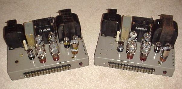
Two amps.
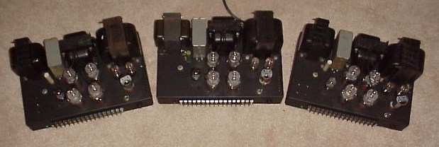
Three amps after painting, one for center channel.
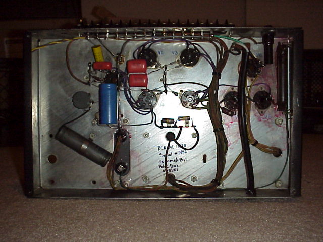
Very well cleaned underneath (Original layout, before bias mod).
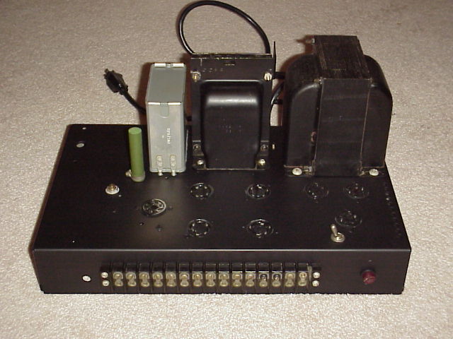
Closeup -no tubes
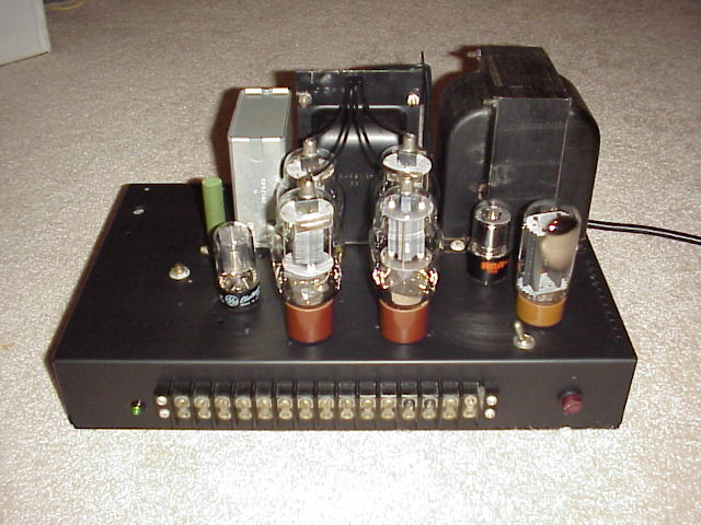
Closeup-with tubes
If you have this kind of amplifier and have improved it or are considering improving it, please do not hesitate to exchange or request information. I would like to hear about your RCA MI-12188A, and add a link from the Official RCA MI-12188A Shrine to your own excellent RCA MI-12188A page.
Contact me: [email protected]
Visits since 06/10/99
[]
FastCounter courtesy of LinkExchnge
[]